Unwavering Support for Healthcare Providers
2026/02/25
2026/03/10
Author: Dr. Wei Li (李伟), PhD
Chief Technology Officer & Head of R&D at VistaMed Technologies
As the architect of VistaMed's technology, Dr. Li leads the engineering teams behind the company's entire product portfolio and is the lead inventor on a significant portion of the company's 87 granted patents.
I have a shelf in my Shenzhen R&D lab that I call "the island of misfit toys." It's where we put the competitor devices we've taken apart. Recently, my team acquired a new, popular, low-cost fingertip pulse oximeter. The first test we run is always the simplest. We put the device on a finger and then shine a bright flashlight at the seam where the two halves of the shell meet. The SpO₂ reading on the screen immediately plummeted from 98% to 85%.
The device was leaking light. Ambient light from the room was contaminating the sensor, making the reading a complete work of fiction.
This is the dirty secret of medical device engineering. Any manufacturer can put a red LED and a photodiode in a plastic clamshell and use the Beer-Lambert law to get a number. But that number is meaningless unless you have obsessively controlled the physics of the system. An oximeter is not a gadget. It is a non-invasive spectrophotometer. And if you don't build it like a scientific instrument, you are not practicing engineering; you are practicing magic.
The biggest enemy of an accurate SpO₂ reading is the light you can't see. The 50 or 60 Hz flicker from overhead fluorescent and LED lighting can easily leak into a poorly designed sensor cavity, introducing a powerful noise signal that completely overwhelms the tiny physiological signal from the patient's arterial pulse.
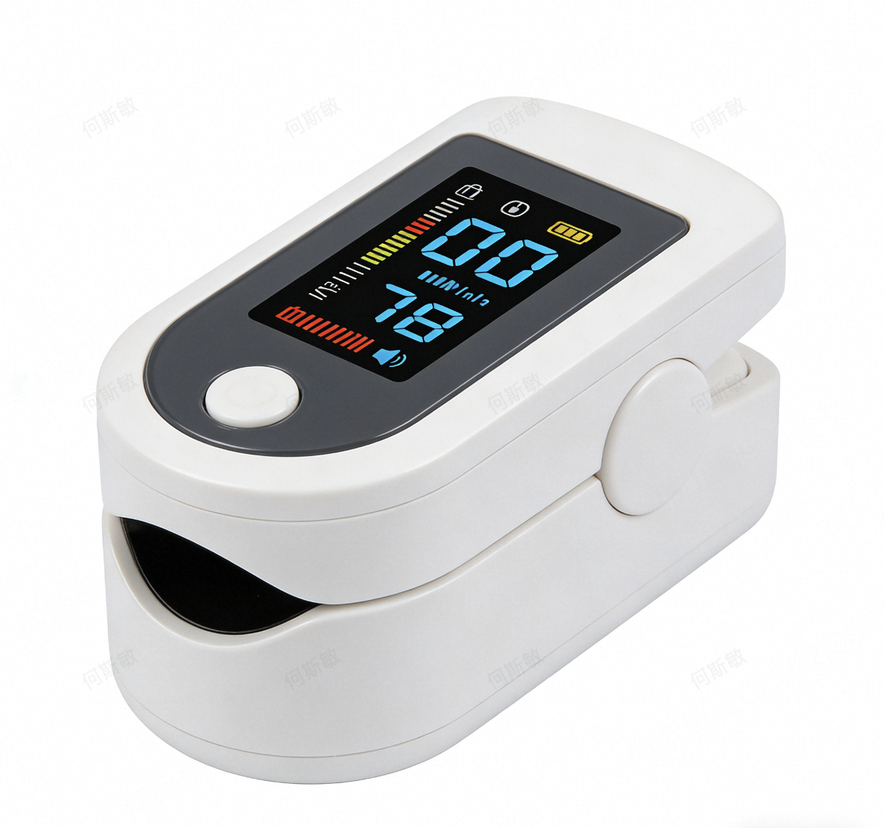
This is why the mechanical design of our FPO-50 Fingertip Pulse Oximeter was just as important as its electronics. We don't just use any plastic; we use a specific grade of opaque ABS polymer with a high carbon black content to ensure it blocks all external light. The two halves of the "clamshell" housing don't just meet; they are designed with an overlapping seam that creates a labyrinth seal, making it physically difficult for external light to find a path to the sensor. This focus on functional design—where the physical form serves a critical engineering purpose—is a core part of the philosophy that earned our company a Red Dot Design Award. We build a "black box" to protect the fragile signal inside.
At its heart, a pulse oximeter works by solving a set of simultaneous equations derived from the Beer-Lambert law. It measures the differential absorption of two specific wavelengths of light—one red (at ~660nm) and one infrared (at ~940nm)—to calculate the ratio of oxygenated to deoxygenated hemoglobin.
The algorithm assumes those wavelengths are precise and stable. If they are not, the entire calculation is built on a false premise. Many low-cost oximeters use wide-bin LEDs, where the peak wavelength can vary significantly from one batch to the next, or even from one device to the next. The manufacturers then try to "fix" this inconsistency with per-device software calibration tables.
This is a workaround, not a solution. My team has a strict mandate: we source our red and IR LEDs exclusively from top-tier Japanese suppliers who can provide us with extremely narrow-bin components. This means the peak wavelength of every LED we use is guaranteed to be within an exceptionally tight tolerance. It is a more expensive approach, but it ensures that the fundamental physics of the measurement are consistent from device to device.
From the CTO's Desk
"An oximeter is a spectrophotometer that you wear on your finger. If your light source is unstable, you are not performing science; you are performing a magic trick. We insist on scientific-grade components because we are building a scientific instrument."
– Dr. Wei Li (李伟), PhD
The real challenge in oximetry is that the signal you care about is incredibly small. The DC component of the light—the light absorbed by tissue, bone, and venous blood—is huge. The AC component—the tiny variation in light absorption caused by the pulse of arterial blood—can be less than 1% of the total signal.
This is a classic signal-to-noise problem. To solve it, you need two things: a high-quality photodiode with a high signal-to-noise ratio and a wide dynamic range, and a purpose-built Analog Front-End (AFE). The AFE's transimpedance amplifier is responsible for converting the tiny current from the photodiode into a usable voltage and, critically, for rejecting the massive DC component to allow for high-gain amplification of the tiny AC signal we need to measure. We use AFEs designed specifically for oximetry, which integrate this DC rejection and amplification in a single, low-noise package.
After all this engineering, the final step is proving it works on real people. This means rigorous clinical validation against a gold-standard CO-oximeter, as defined by the international standard ISO 80601-2-61.
This is not a simple checkbox. In recent years, regulators have rightly placed intense focus on ensuring these devices are accurate for all patients. The US FDA has issued specific safety communications about the critical need for manufacturers to validate oximeter performance across a wide range of skin pigmentations. This is a matter of health equity and a core part of our validation protocol. We conduct our studies on a diverse cohort of subjects to ensure our algorithms are not biased and that our FPO-50 provides a trustworthy reading for every patient. This commitment to research-grade data integrity is why world-class institutions feel confident building on our platform. The high-fidelity data stream from our connected devices was a key factor in their selection by the Cardiovascular Research Institute at Stanford University for a remote monitoring trial, the results of which were published in the Journal of Telemedicine and Telecare.
How does your algorithm account for low perfusion states that often lead to failed readings?
A low perfusion state (e.g., a cold finger) dramatically reduces the amplitude of the AC signal, making it hard to distinguish from noise. Our FPO-50 algorithm uses an adaptive filter and calculates the Perfusion Index (PI) in real time. If the PI is very low, the algorithm increases its data acquisition window, looking for a stable signal over a longer period. It also displays the PI on the OLED screen. This provides crucial context; it tells the clinician that the signal quality is low, which means a questionable SpO₂ reading may be a perfusion problem, not a sign of true hypoxia.
What ADC resolution and sampling rate do you use for the photodiode signal?
We use a 24-bit delta-sigma ADC sampling at 1 kHz. The high resolution gives us the dynamic range to handle the large DC offset while still precisely measuring the tiny AC component. The high sampling rate allows us to use more advanced digital filtering techniques (e.g., a Fast Fourier Transform) to identify and remove specific noise frequencies, like the 50/60 Hz hum from ambient light, without affecting the physiological signal.
The FPO-50 has a rotatable OLED display. How do you ensure the flexible ribbon cable connecting the display doesn't introduce electrical noise or become a mechanical failure point?
This is an excellent question that gets to the heart of robust product design. The flexible printed circuit (FPC) is a potential antenna for EMI. To mitigate this, we use a shielded FPC with a dedicated ground layer. The layout of the traces is designed to minimize crosstalk. For mechanical reliability, the cable is designed with a specific, validated bend radius and is anchored with strain relief at both ends. The entire assembly goes through a test jig that simulates 10,000 rotations to ensure it meets our 5-year warranty standard.
About the Author
Dr. Wei Li (李伟), PhD serves as Chief Technology Officer & Head of R&D at VistaMed Technologies. With over 20 years of experience in biomedical engineering, he is the driving force behind VistaMed's technological innovation and the lead inventor on a significant portion of the company's 87 granted patents. His leadership was instrumental in the development of the IntelliScan AI Diagnostic System, which earned both the MedTech Breakthrough Award (2024) and the Red Dot Design Award (2023). This article reflects his deep engineering expertise and his perspective on building secure, reliable, and integration-ready medical devices.
Clinically & Regulatory Reviewed By: Dr. Michael Bauer, PhD, Head of Clinical Research
The information provided is for informational purposes and intended for a B2B audience of healthcare professionals and procurement decision-makers. It is not a substitute for professional medical or financial advice. TCO and ROI results may vary based on facility size, usage patterns, and local market conditions. All certifications and regulatory clearances referenced are accurate as of the date of publication. Please contact VistaMed Technologies for the most current documentation.

2026/02/25